Lab 5: Interrupts
Introduction
In this lab, I used an MCU in order to determine the speed of a motor by reading interrupts from quandrature encoder. Quandrature encoders measure the relative or absolute angle of a motor tracking how quickly the patterned disk added onto the motor rotates. Two sensors are 90 degrees of of phase to determine direction and speed of rotation with high resolution. The motor has 408 pulses per rotation and rotates at a speed of approximately 2 rev/s when 10V is supplied to the motor.
The main objective of this lab was to determine (and print out) the speed of the motor and direction, updating every 1Hz.
MCU Design and Testing Methodology.
The design was developed by using interrupts. Interrupts were used both from the signals from the encoders and the timer.
The interrupt for the quad encoder signals would fire when the system recorded a signal from the B or A signal, where the design detected all edges of the encoder pulses to achieve high resolution. The current state on the encoder would update respectively. A lookup table was implemented in order to create the counter logic, indicating when the encoder has changed states. The lookup table starts with 4 bits indicating the next state transitions from 00, where 0 represents an illegal state switch, 1 represents clockwise increase, and -1 represents counterclockwise decrease. The following 4 bits indicate the next state transitions for 01, then 10, and ending with 11. The indexing of the lookup table relies on the previous state shifted left two bits and the current state in the two least significant bits. The values from the lookup table are then added to the encoder count and the previous state gets the current state.
The interrupt for the timer fires every millisecond and once it counts to 1000 ms (1 second), the count difference is calculated and used to calculate the revolutions per second. The count difference is divided by 1632 because the design is decoding the rising and falling edges of A and B (4 total), and since the motor has 408 pulses per rotation. The rps is printed out every second and the timer resets to begin sampling again.
Hardware Implementation
The layout of the system was fairly simple. The MCU was directly connected to the pins of the motor, no external breadboarding was required.
Technical Documentation
The code for this lab can be found in this Github repository. This contains the code for main.c file as well as external libraries used.
Schematic
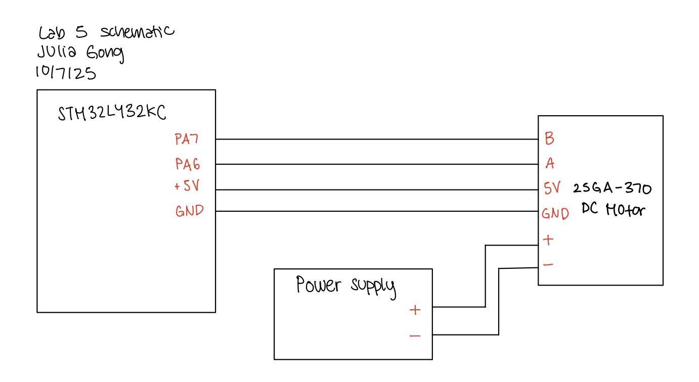
The schematic below depicts the connections between the MCU and the motor.
The flow chart below shows how interrupts are handled in the system. 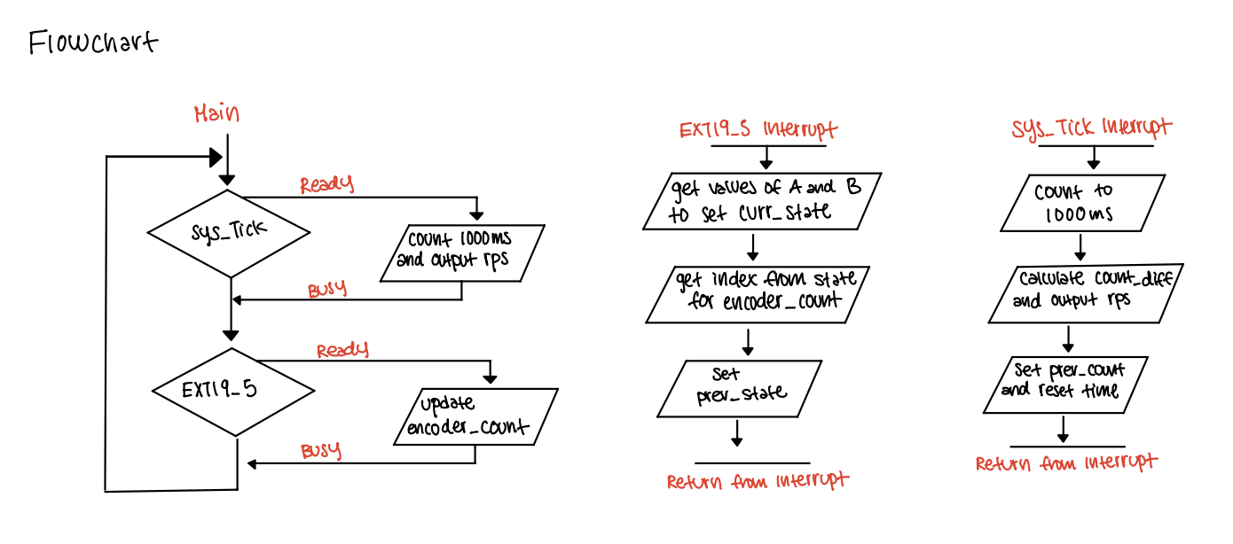
Results and Discussion
The system was able to correctly calculate the angular velocity of the motor in both the clockwise and counter clockwise directions. When the supply voltage was 10V, the print in the debugger read around +- 2 rev/s (depending on the direction). Additionally, the ancular velocity increased and decreased in respones to voltage supplied to the motor and read 0 when the power supply was off.
Oscilloscope Interrupt Pin Toggling
In order to observe the tradeoffs between using interrupts and polling to measure the angular velocity, I wrote some code for polling so I can toggle a pin for both to compare the toggling frequency for interrupts and polling.
The oscilloscope trace for interrupts shows a frequency of 2.4kHz, indicating the speed in which the interrupts are occurring. This means that for the polling to be able to sample all the encoder state changes, it must be sampling at least 4.8kHz (two times the frequency of the interrupts) to sample all the state changes and avoid aliasing. 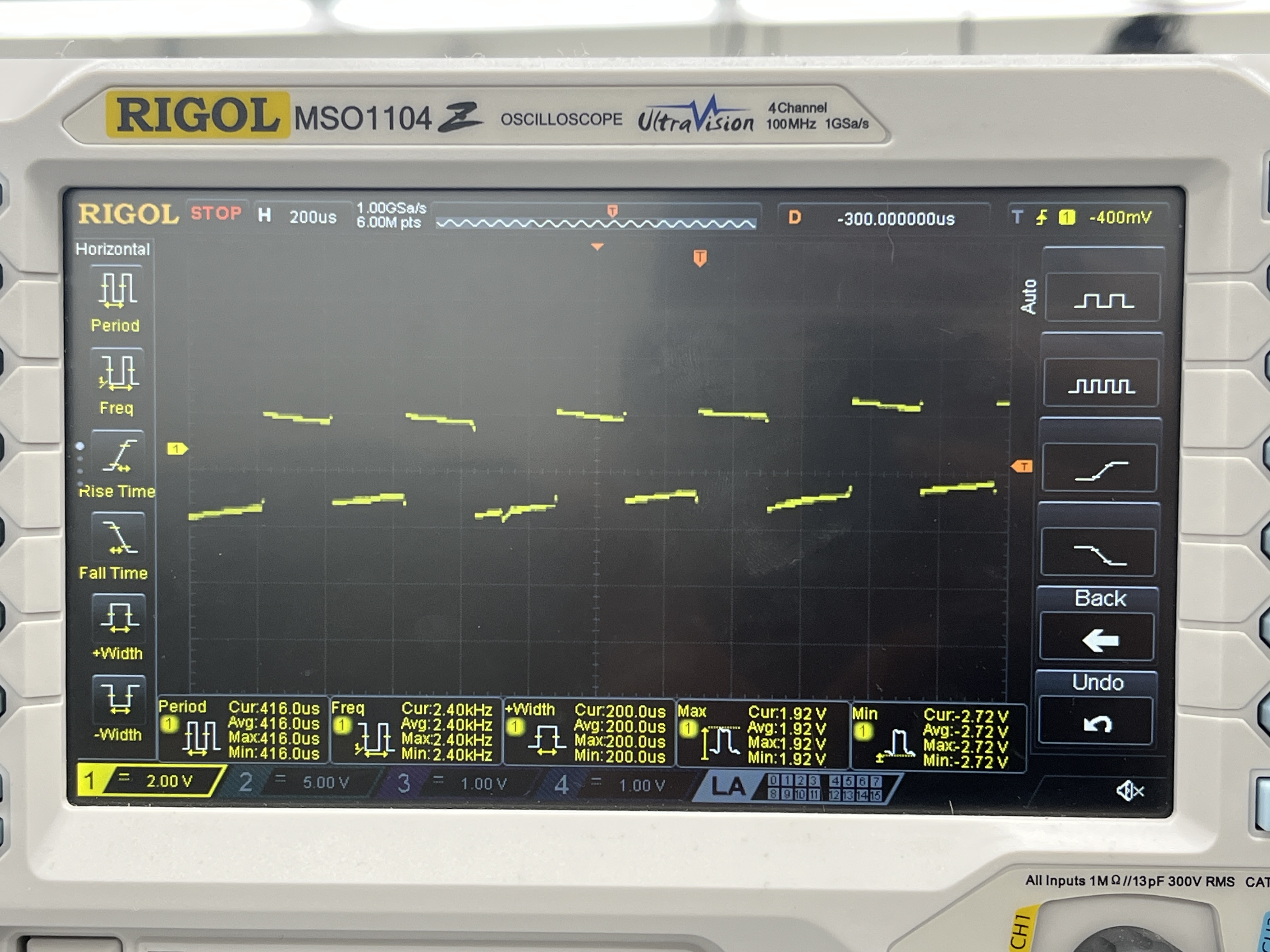
The oscilloscope trace for the polling shows are frequency of 2.20kHz as well as some breaks in the squre waves. This is likely because the system is polling too slowly to detect all the state changes. 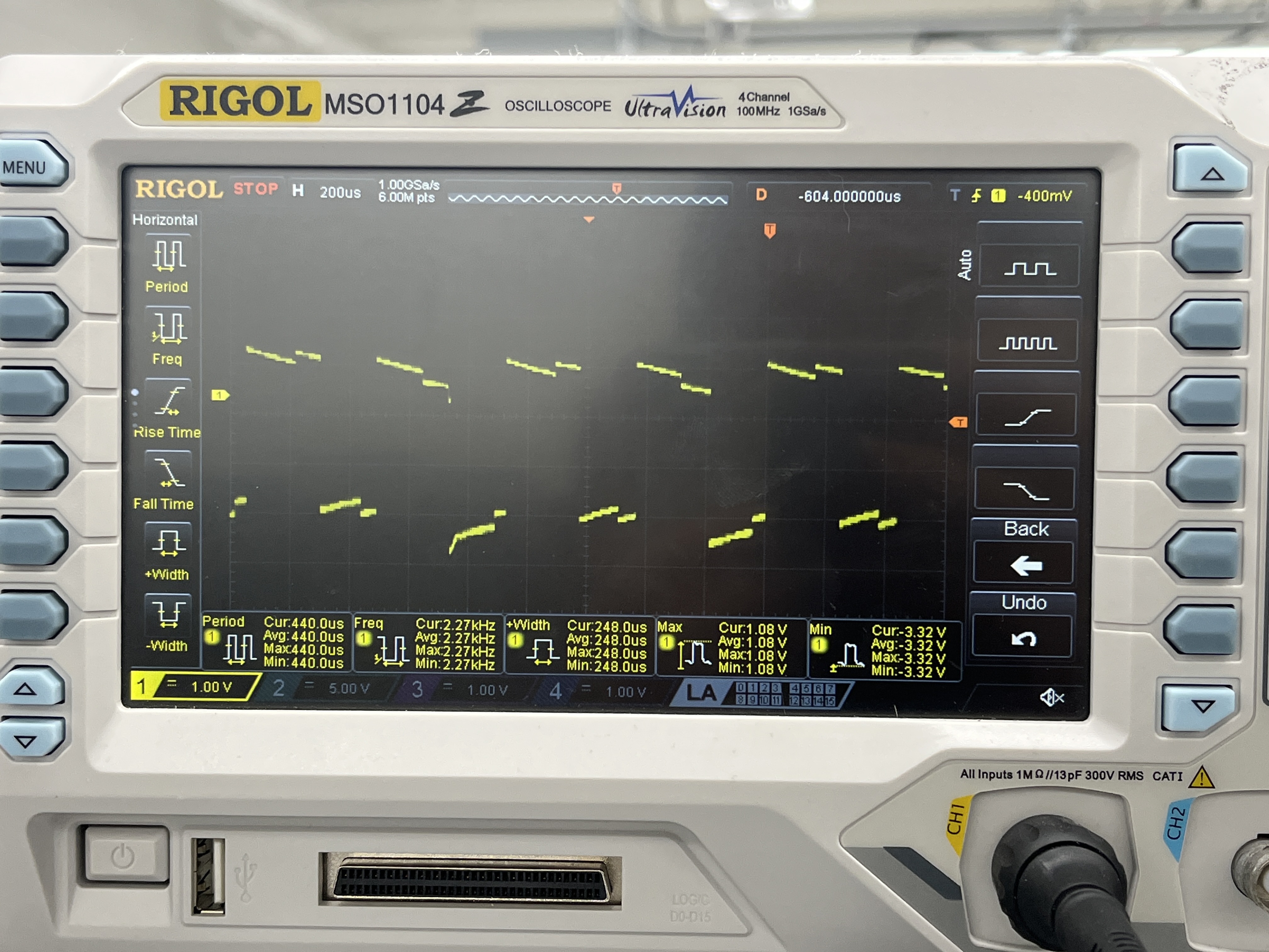
Conclusion
I was able to design a system using interrupts to calculate the angular velocity of a motor using the rising and falling edges of the encoders! This lab took a total of 8 hours.
AI Prototype Summary
For my AI prototype, I prompted ChatGPT with: Write me interrupt handlers to interface with a quadrature encoder. I’m using the STM32L432KC, what pins should I connect the encoder to in order to allow it to easily trigger the interrupts?
ChatGPT responded with the correct pins that can be used to connect the encoder to trigger interrupts, howevever, the interrupt handlers did not run. ChatGPT suggested that I use the TIM encoder mode and to not use EXTI/GPIO interrupts unless they were necessary. I found this interesting since I was using EXTI interrupts in this lab and thought that they did they job well.