Lab 4: Digital Audio
Introduction
In this lab, I used the timers in an STM32L432KC microcontroller to generate square waves by toggling a GPIO pin at specific frequencies and durations. These frequencies and durations were used to create digital audio. This involved reading and understanding the MCU datasheet in order to write a C library from scratch.
MCU Design and Testing Methodology.
The design was developed by using two timers on the MCU: TIM16 and TIM6. TIM16 was used to create a PWM signal for the frequencies while TIM6 was used to calculate the delay in ms.
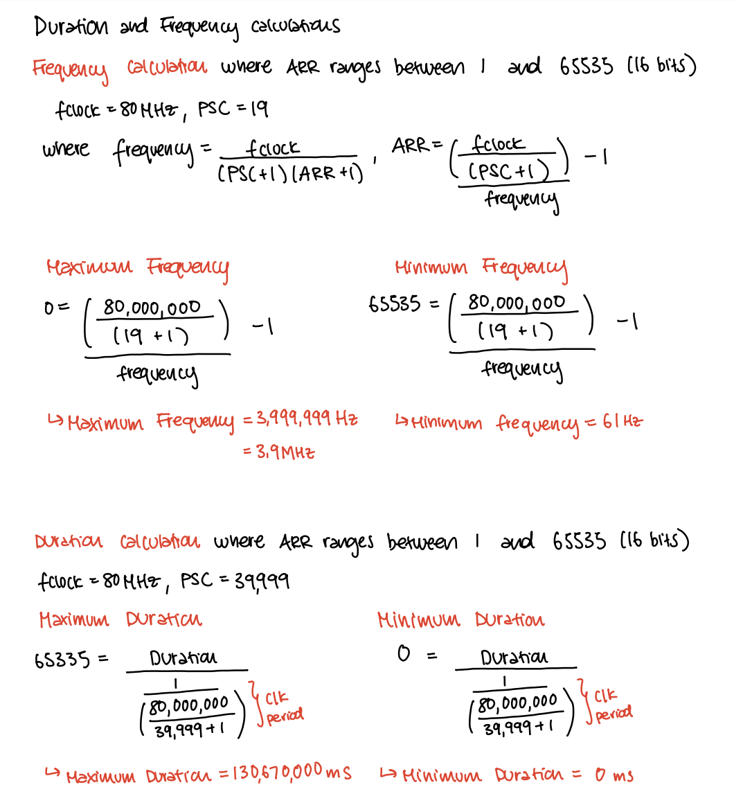
The maximum and minimum frequencies and durations for the system were calculated below. TIM16 used a prescalar value of 19 in order to divide the system clock into a 4MHz clock and TIM6 used a prescalar value of 39,999 in order to divide the system clock into a 2KHz clock.
In addition to calculations, the frequency of the square waves will be verified using the oscilloscope.
This image shows that the pitches for frequencies in the range 220-1000 Hz, as well as a couple frequencies above and below are accurate within 1%. 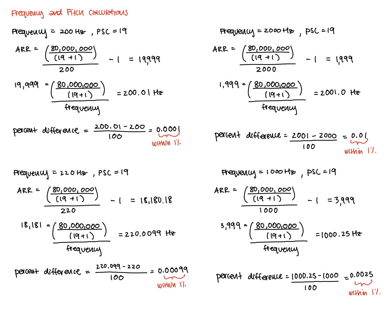
Hardware Implementation
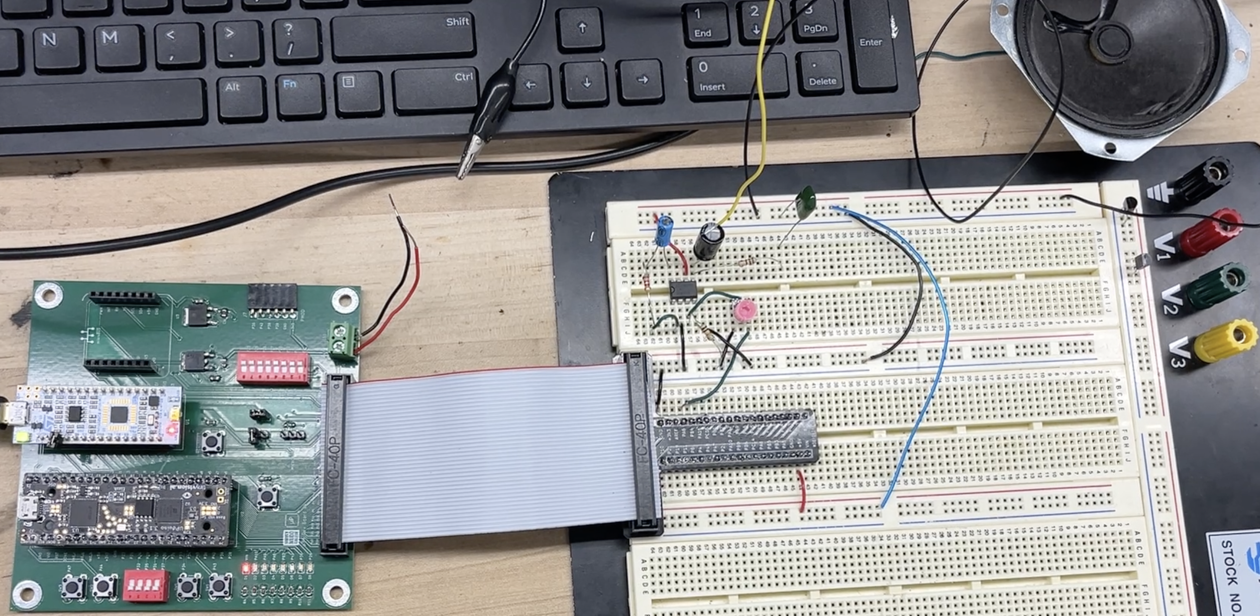
The components of this lab consisted of a LM386 op-amp, a 10kΩ potentiometer, and a 8Ω speaker. The op-amp was implemented to amplify the output signal from the MCU pin (PA6) and the potentiometer was used to adjust the volume of the system.
Technical Documentation
The code for this lab can be found in this Github repository. This contains the code for the C and Header files for the main module, RCC, GPIO, FLASH, TIM6, and TIM16.
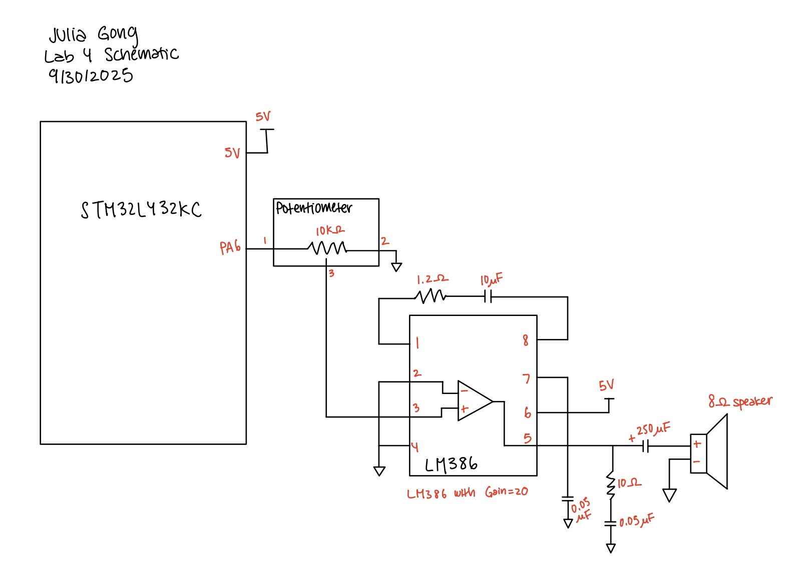
Schematic
The schematic below depicts the pin assignments and connections for the MCU, potentiometer, op-amp, and speaker system.
Results and Discussion
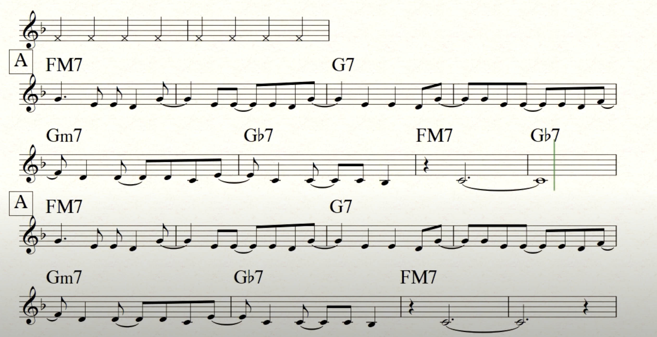
The digital audio system was able to play Fur Elise without sounding very crackly. Additionally, I was able to transpose a melody from one of my favorite jazz songs. Try to guess the song!
Oscilloscope Frequency Verification
In order to verify the frequencies produced by my design, I measured the frequency of the PA6 pin. To test the range of frequncies, I decided to test 200 Hz and 2000 Hz.
The oscilloscope trace of the 200 Hz PWM input, shows a square wave output from the PA6 pin where the output frequency is exactly 200 Hz! 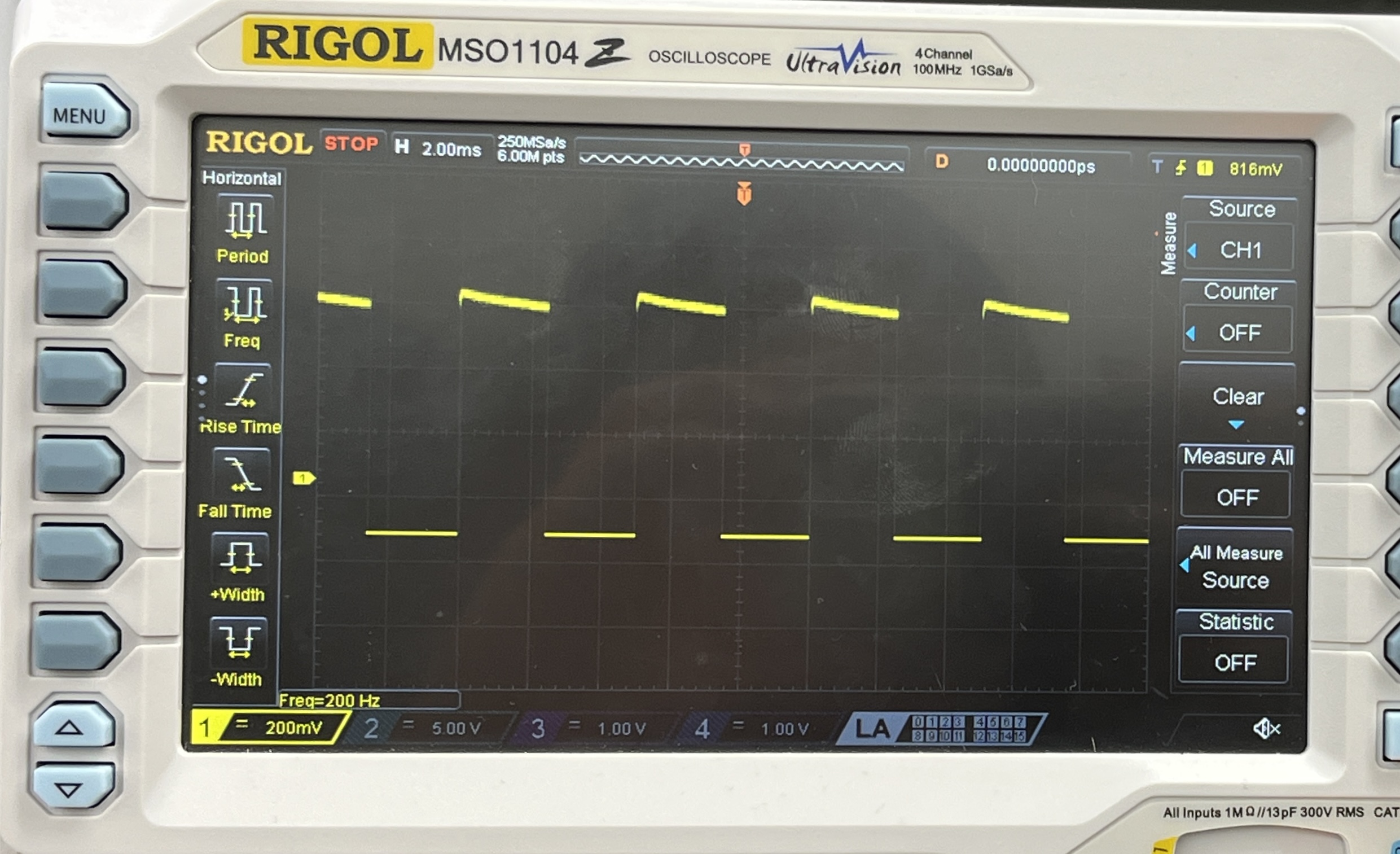
The oscilloscope trace for the 2000 Hz PWM input showed the expected output of 2000 Hz. This shows that the design was able to accurately output frequencies less than 1% 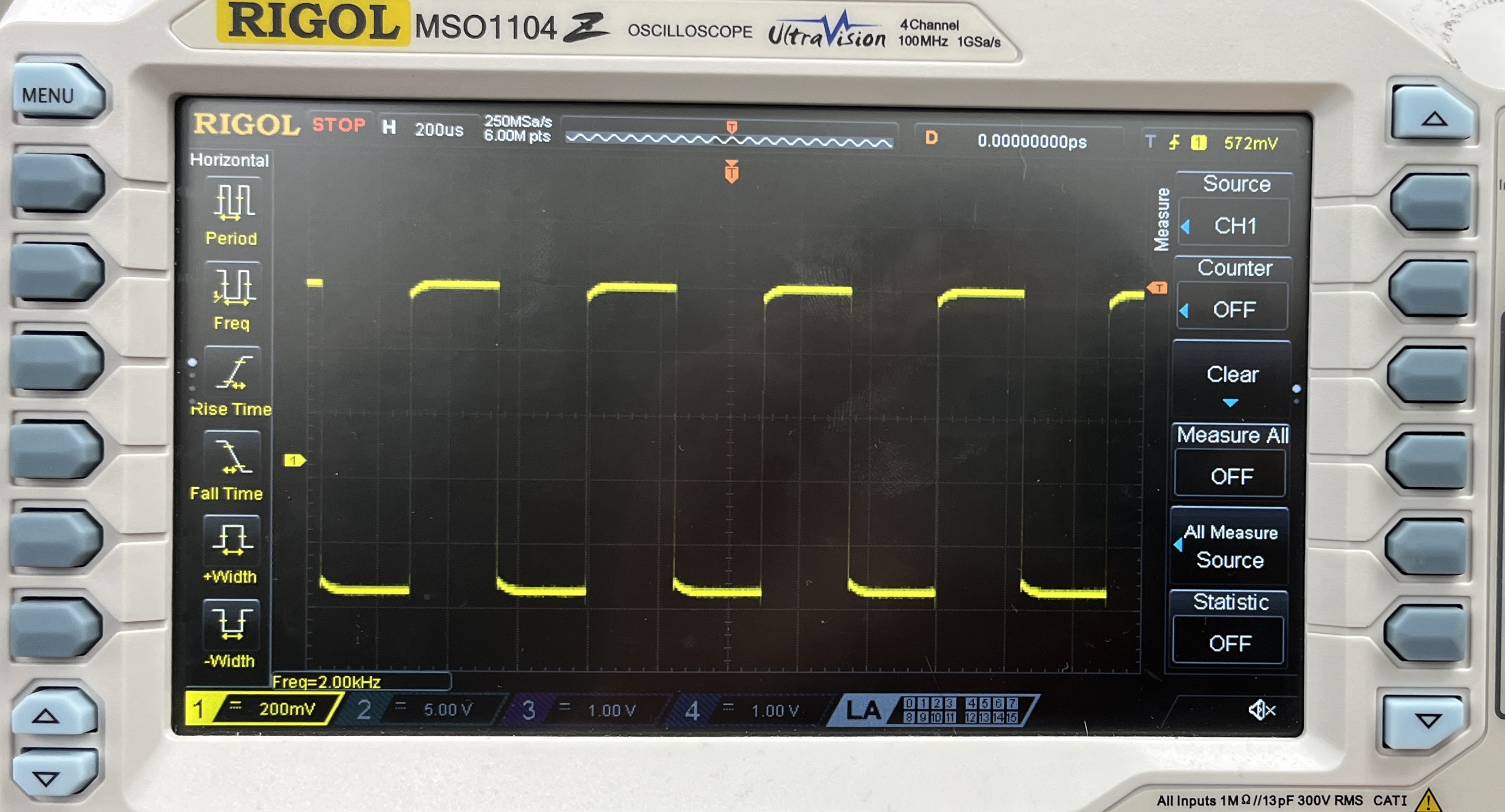
Conclusion
The design was successfully able to produce square waves at different frequencies using the timers and pins on the MCU. It was super exciting to hear the the songs play smoothly. For a while, I was able to hear my songs play but they sounded very crackly. I thought it was because my code for the frequency was incorrect, but I figured out that it was because my op-amp pins weren’t grounded.
This lab took a total of 12 hours.
AI Prototype Summary
For the AI prototype, I prompted ChatGPT with: What timers should I use on the STM32L432KC to generate frequencies ranging from 220Hz to 1kHz? What’s the best choice of timer if I want to easily connect it to a GPIO pin? What formulae are relevant, and what registers need to be set to configure them properly?
The response that I got from ChatGPT was very helpful because it provided me a list of all the timers with descriptions for their purposes. It also generated the timer frequency formula and provided an example calculation.